
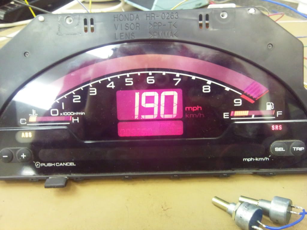
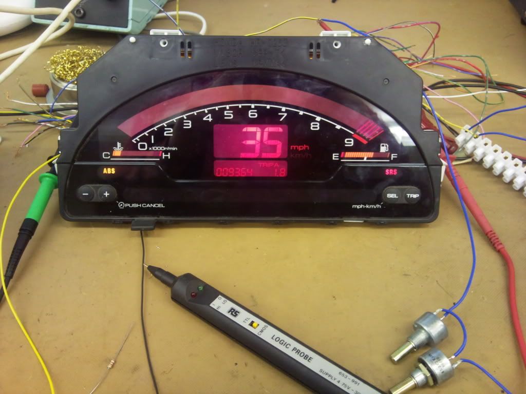
Another just to show i was controlling the fuel and speed.
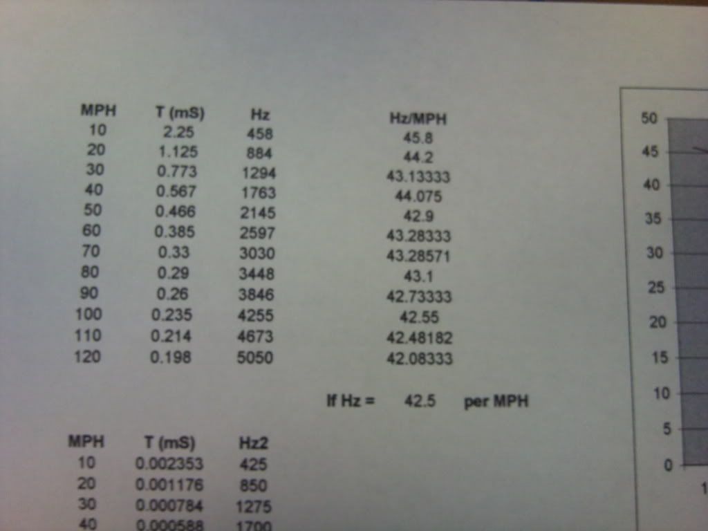
I made up a chart and two graphs of what the speedo is doing at what freq, from this is took the average freq is 42.5 per mph.
The only thing left now is the temp gauge. I first tried this in the same way as the fuel guage thinking it would work off an analog voltage dependant on the resistance value from the temp sensor, which ended up as an epic fail. It would only show a full temp or nothing, which told me that this is a digital logic circuit. after a quick check to see that it was 5v it was confirmed. So im just wanting to check as with my ocilliscope it looks to be telling theres the one signal cable running to the temp sensor which is also the feedback line for the logic then the unit is just grounded.
So all im going to do now is get an s2000 temp sensor to hook up and check how accurate this will be.
I have done everything without buying any converter units etc..
So it can be done, and tbh once you start it if you have the right gear (logic probe, multimeter, freq generator, occiliscope etc) its not all that hard. I didnt manage to get any pics today but tommoro il take some and get them posted up!!
The next part will be making a face for it so that it fits the dial surround nice and neatly!!
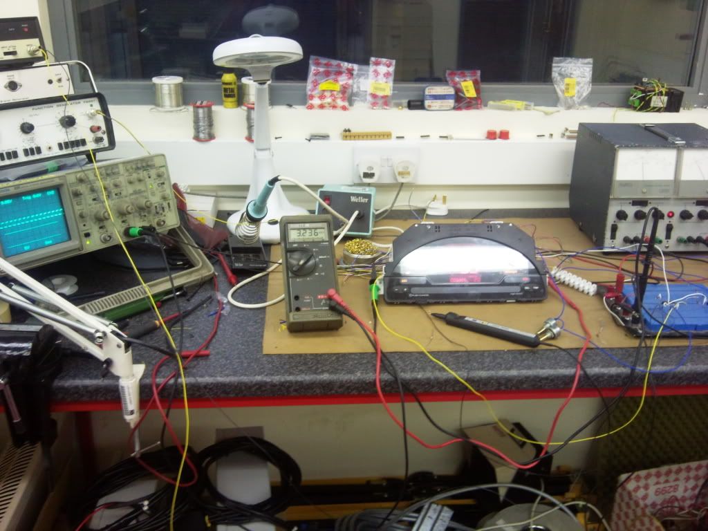
Just a small picture of my work station!